 |  |

The layer above the Network Access Layer in the protocol hierarchy is the Internet Layer. The Internet Protocol (IP) is the most important protocol in this layer. The release of IP used in the current Internet is IP version 4 (IPv4), which is defined in RFC 791. There are more recent versions of IP. IP version 5 is an experimental Stream Transport (ST) protocol used for real-time data delivery. IPv5 never came into operational use. IPv6 is an IP standard that provides greatly expanded addressing capacity. Because IPv6 uses a completely different address structure, it is not interoperable with IPv4. While IPv6 is a standard version of IP, it is not yet widely used in operational, commercial networks. Since our focus is on practical, operational networks, we do not cover IPv6 in detail. In this chapter and throughout the main body of the text, "IP" refers to IPv4. IPv4 is the protocol you will configure on your system when you want to exchange data with remote systems, and it is the focus of this text.
The Internet Protocol is the heart of TCP/IP. IP provides the basic packet delivery service on which TCP/IP networks are built. All protocols, in the layers above and below IP, use the Internet Protocol to deliver data. All incoming and outgoing TCP/IP data flows through IP, regardless of its final destination.
The Internet Protocol is the building block of the Internet. Its functions include:
Defining the datagram, which is the basic unit of transmission in the Internet
Defining the Internet addressing scheme
Moving data between the Network Access Layer and the Transport Layer
Routing datagrams to remote hosts
Performing fragmentation and re-assembly of datagrams
Before describing these functions in more detail, let's look at some of IP's characteristics. First, IP is a connectionless protocol. This means that it does not exchange control information (called a "handshake") to establish an end-to-end connection before transmitting data. In contrast, a connection-oriented protocol exchanges control information with the remote system to verify that it is ready to receive data before any data is sent. When the handshaking is successful, the systems are said to have established a connection. The Internet Protocol relies on protocols in other layers to establish the connection if they require connection-oriented service.
IP also relies on protocols in the other layers to provide error detection and error recovery. The Internet Protocol is sometimes called an unreliable protocol because it contains no error detection and recovery code. This is not to say that the protocol cannot be relied on -- quite the contrary. IP can be relied upon to accurately deliver your data to the connected network, but it doesn't check whether that data was correctly received. Protocols in other layers of the TCP/IP architecture provide this checking when it is required.
The TCP/IP protocols were built to transmit data over the ARPAnet, which was a packet-switching network. A packet is a block of data that carries with it the information necessary to deliver it, similar to a postal letter, which has an address written on its envelope. A packet-switching network uses the addressing information in the packets to switch packets from one physical network to another, moving them toward their final destination. Each packet travels the network independently of any other packet.
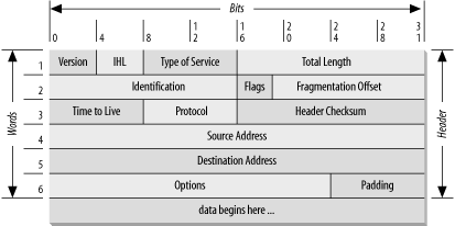
The datagram is the packet format defined by the Internet Protocol. Figure 1-5 is a pictorial representation of an IP datagram. The first five or six 32-bit words of the datagram are control information called the header. By default, the header is five words long; the sixth word is optional. Because the header's length is variable, it includes a field called Internet Header Length (IHL) that indicates the header's length in words. The header contains all the information necessary to deliver the packet.

The Internet Protocol delivers the datagram by checking the Destination Address in word 5 of the header. The Destination Address is a standard 32-bit IP address that identifies the destination network and the specific host on that network. (The format of IP addresses is explained in Chapter 2, "Delivering the Data".) If the Destination Address is the address of a host on the local network, the packet is delivered directly to the destination. If the Destination Address is not on the local network, the packet is passed to a gateway for delivery. Gateways are devices that switch packets between the different physical networks. Deciding which gateway to use is called routing. IP makes the routing decision for each individual packet.
Internet gateways are commonly (and perhaps more accurately) referred to as IP routers because they use Internet Protocol to route packets between networks. In traditional TCP/IP jargon, there are only two types of network devices -- gateways and hosts. Gateways forward packets between networks, and hosts don't. However, if a host is connected to more than one network (called a multi-homed host), it can forward packets between the networks. When a multi-homed host forwards packets, it acts just like any other gateway and is in fact considered to be a gateway. Current data communications terminology makes a distinction between gateways and routers,[6] but we'll use the terms gateway and IP router interchangeably.
[6]In current terminology, a gateway moves data between different protocols, and a router moves data between different networks. So a system that moves mail between TCP/IP and X.400 is a gateway, but a traditional IP gateway is a router.
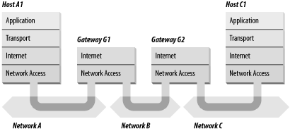
Figure 1-6 shows the use of gateways to forward packets. The hosts (or end systems) process packets through all four protocol layers, while the gateways (or intermediate systems) process the packets only up to the Internet Layer where the routing decisions are made.

Systems can deliver packets only to other devices attached to the same physical network. Packets from A1 destined for host C1 are forwarded through gateways G1 and G2. Host A1 first delivers the packet to gateway G1, with which it shares network A. Gateway G1 delivers the packet to G2 over network B. Gateway G2 then delivers the packet directly to host C1 because they are both attached to network C. Host A1 has no knowledge of any gateways beyond gateway G1. It sends packets destined for both networks C and B to that local gateway and then relies on that gateway to properly forward the packets along the path to their destinations. Likewise, host C1 sends its packets to G2 to reach a host on network A, as well as any host on network B.
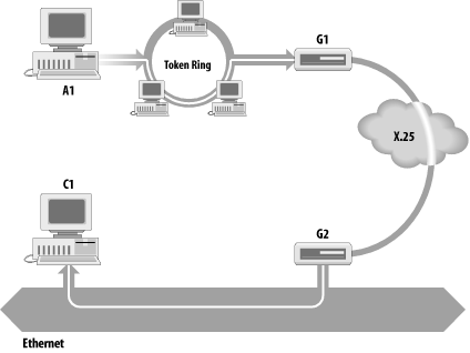
Figure 1-7 shows another view of routing. This figure emphasizes that the underlying physical networks a datagram travels through may be different and even incompatible. Host A1 on the token ring network routes the datagram through gateway G1 to reach host C1 on the Ethernet. Gateway G1 forwards the data through the X.25 network to gateway G2 for delivery to C1. The datagram traverses three physically different networks, but eventually arrives intact at C1.

As a datagram is routed through different networks, it may be necessary for the IP module in a gateway to divide the datagram into smaller pieces. A datagram received from one network may be too large to be transmitted in a single packet on a different network. This condition occurs only when a gateway interconnects dissimilar physical networks.
Each type of network has a maximum transmission unit (MTU), which is the largest packet that it can transfer. If the datagram received from one network is longer than the other network's MTU, the datagram must be divided into smaller fragments for transmission. This process is called fragmentation. Think of a train delivering a load of steel. Each railway car can carry more steel than the trucks that will take it along the highway, so each railway car's load is unloaded onto many different trucks. In the same way that a railroad is physically different from a highway, an Ethernet is physically different from an X.25 network; IP must break an Ethernet's relatively large packets into smaller packets before it can transmit them over an X.25 network.
The format of each fragment is the same as the format of any normal datagram. Header word 2 contains information that identifies each datagram fragment and provides information about how to re-assemble the fragments back into the original datagram. The Identification field identifies what datagram the fragment belongs to, and the Fragmentation Offset field tells what piece of the datagram this fragment is. The Flags field has a "More Fragments" bit that tells IP if it has assembled all of the datagram fragments.
When IP receives a datagram that is addressed to the local host, it must pass the data portion of the datagram to the correct Transport Layer protocol. This is done by using the protocol number from word 3 of the datagram header. Each Transport Layer protocol has a unique protocol number that identifies it to IP. Protocol numbers are discussed in Chapter 2, "Delivering the Data".
You can see from this short overview that IP performs many important functions. Don't expect to fully understand datagrams, gateways, routing, IP addresses, and all the other things that IP does from this short description; each chapter will add more details about these topics. So let's continue on with the other protocol in the TCP/IP Internet Layer.
An integral part of IP is the Internet Control Message Protocol (ICMP) defined in RFC 792. This protocol is part of the Internet Layer and uses the IP datagram delivery facility to send its messages. ICMP sends messages that perform the following control, error reporting, and informational functions for TCP/IP:
When datagrams arrive too fast for processing, the destination host or an intermediate gateway sends an ICMP Source Quench Message back to the sender. This tells the source to stop sending datagrams temporarily.
When a destination is unreachable, the system detecting the problem sends a Destination Unreachable Message to the datagram's source. If the unreachable destination is a network or host, the message is sent by an intermediate gateway. But if the destination is an unreachable port, the destination host sends the message. (We discuss ports in Chapter 2, "Delivering the Data".)
A gateway sends the ICMP Redirect Message to tell a host to use another gateway, presumably because the other gateway is a better choice. This message can be used only when the source host is on the same network as both gateways. To better understand this, refer to Figure 1-7. If a host on the X.25 network sent a datagram to G1, it would be possible for G1 to redirect that host to G2 because the host, G1, and G2 are all attached to the same network. On the other hand, if a host on the token ring network sent a datagram to G1, the host could not be redirected to use G2. This is because G2 is not attached to the token ring.
A host can send the ICMP Echo Message to see if a remote system's Internet Protocol is up and operational. When a system receives an echo message, it replies and sends the data from the packet back to the source host. The ping command uses this message.

Copyright © 2002 O'Reilly & Associates. All rights reserved.