Tools Required:
- Standard assortment of metric and SAE wrenches and sockets
Dial gauge
Big vise
Press
Feeler Gauge
7/16" drill bit
1/4" NPT tap (standard pipe thread)
|
Materials Required:
|
 |
All materials should be available at a minimal cost from your local auto
parts store
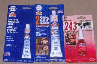
Gasket maker - Such as FORM-A-GASKET from Permatex.
Gear alignment goop - Such as Prussian Blue from Permatex.
Loctite
Teflon Tape
80W90 gear oil
|
Products Required:
- ARB Air Locker (2)
- Cost can range from $550 to $725 each depending on where you
purchase them.
For a 1995 Defender 90, the 24 spline ARB Model RD56 is used in
both the front and rear.
For a 1990 Range Rover, the 10 spline ARB Model RD03 is used in
the rear.
- Take care: Some 90's have a 10-spline rear axle. Check first
- Timken bearings
- 2 sets in the rear and 2 sets in the front, each set has 1 cup
and 1 cone.
Each set should cost around $10. For a 1995 Defender 90, each set
consists of one # LM102949 and one #
LM102910.
For a 1990 Range Rover, each set consists of one # LM501349 and
one # LM501310.
- Air Compressor
- ARB compressor is around $200 (or) Quick Air II compressor is
around $250
- Air Tank
- Not needed if you use the ARB compressor because of it has a
small on board tank.
The Sun Performance 2.5 gallon tank is about $70
- Air fixtures
- A variety of hoses and connectors are needed, depending on your
exact install. They can be purchased separately or you can buy the
Sun performance tank installation kit for about $90 and it should
have everything you need, including a pressure switch and a pressure
gauge to mount on the dash.
- Wiring
- You need some 14 and 10 gauge wire as well as a good selection
of spade end connectors. You'll probably want an auxiliary fuse
block as well.
Project Overview:
We decided to divide up the install into three separate projects, allowing
us to more easily fit it into our available time
rather than trying to go for some marathon install over a weekend and
hope that the truck was driveable on Monday
morning. The three projects were to install the rear diff, install the
front diff and install the air system. Our project
team consisted of two guys - Greg Haugen and Dave Gaboury. Greg provided
the know-how and experience (having
put an ARB locker in the rear diff of his Range Rover). This job can be
done by one person but two makes it go faster
and there are plenty of times where an extra set of hands are useful.
Having another set of eyes to double check your
work is also handy.
We started by installing the rear diff. We did this on a Saturday over
a 6 hour period (including a break for lunch). All
tools and materials were obtained before we started so there was no wasted
time running out to the store for
emergency supplies. The front diff was another Saturday project, taking
just a little longer than the rear. The diff itself
is the same in the front but it's a bit more work getting the third member
off and back on. The air system is quite a
different project. While the diffs themselves are just a matter of following
the steps, the air system is a maze of
decisions and trade offs that you'll have to make, starting with what
parts you want to use and continuing with
decisions on where to install them. Remember that the air setup discussed
here is just one option and you'll have to
decide what fits your needs. This air system was installed in bits and
pieces as time permitted, but if you wanted to do
it all in one shot, you can plan on killing another Saturday.
|
 |
Part 1: Installing the rear ARB locker
Step 1:
Prepare work area. Assemble all the required materials and tools in
a warm, dry garage. If you live in North Dakota, this can be a challenge.
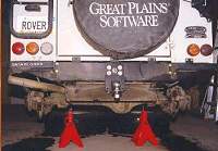
Get the rear of the truck up on jack stands and remove both rear wheels.
|
 |
Step 2:
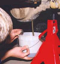
Unscrew the differential drain plug and drain all of the oil.
|
 |
Step 3:
Remove the rear hub driving member bolts on both wheels. They should
have Loctite on the bolts, so expect them to
be a bit tight.
|
 |
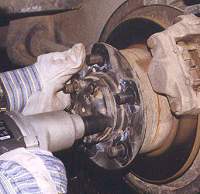
Pull out the hub driving member and the attached half shaft
on both sides. They only have to be pulled out far enough for the half shafts
to be clear of the third member. |
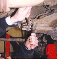 |
Step 5: Remove all four bolts that secure the prop shaft to
the rear differential. You can tie up the back of the prop shaft to the
A-frame to keep it out of the way. |
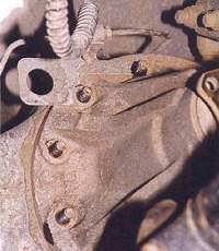 |
Remove the nuts that attach the third member to the axle casing.
Note the bracket on the top nuts that supports the brake lines. Just push
the bracket out of the way. You may want to mark a spot on the pinion housing
where you'll be drilling later on. The spot should be on the top right hand
side of the pinion, near the brake line bracket. |
 |
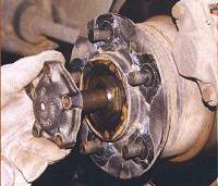
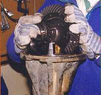
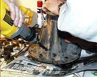
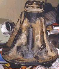
Pull the third member forward off of the axle casing. It will
be difficult to start because of the sealant that was used when it was assembled.
You may need to pry it open to get it started. |
 |
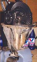
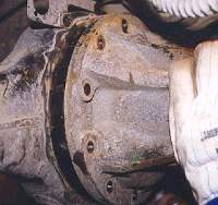
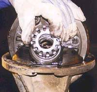
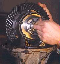
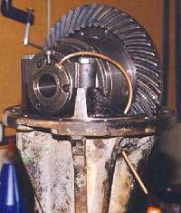
The entire differential is secured to the pinion housing and
will come out all as one unit (the third member). It will be quite heavy,
so be prepared to lower it carefully. Here's what it looks like when it's
removed. |
|
|
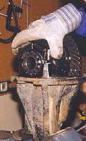
Secure the pinion housing in a heavy duty vise. |
 |
You need to remove both of the carrier bearing caps. Before
doing so, you should mark one of them to be sure you get it back on the
same side because they are milled specifically for a given side. Remove
the two bolts from each side. |
|
|
Lift off both of the carrier bearing caps. |
 |
Remove the bearing nut from each side by giving them an easy
tap upwards. |
 |
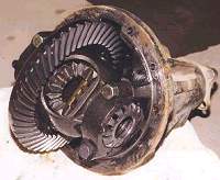
Now the entire differential can be lifted out of the pinion
housing. Hang on to both bearing cups since they are free to fall off. |
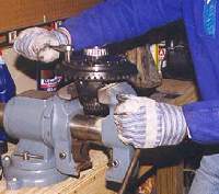 |
Put the differential in the vise with the crown ring facing
up. Remove all of the bolts that secure the crown ring. |
 |
The crown ring fits snuggly onto the carrier, so you'll have
to coax it off with a rubber mallet (or a 2X4). Take care not to mark the
gears on the crown ring. |
 |
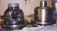
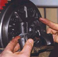
Separate the crown ring from the carrier. The crown ring will
be reused and the carrier will be completely replaced by the ARB differential. |
 |
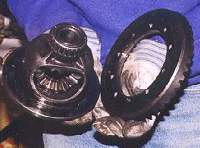
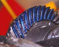
Here's a comparison of the original Land Rover differential
(left) and the ARB differential (right). |
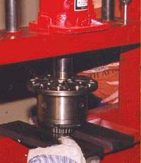 |
Now it's time to put new carrier bearings on the ARB differential.
Since the carrier shaft extends past the bearing on the side away from the
flange, you might find it easier to press that one on first. Align the press
plates on the edge of the bearing as shown so the carrier shaft can extend
past the bearing. |
 |
Here's what the first bearing should look like. |
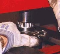 |
Now push the bearing on the other side of the carrier. You
can rest the carrier flange on the press plates as shown. |
 |
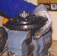
The crown wheel can now be bolted onto the ARB carrier. Since
the crown wheel fits snuggly, you'll have to line it up carefully. The Land
Rover workshop manual suggests that the crown wheel can be easier to position
if you heat it up a bit, either with hot water or by putting it in the oven.
Use Loctite on the bolts. |
 |
Tightening the bolts that attach the crown ring is a bit of
a chore if your vise isn't large enough to fit around the middle of the
carrier. If it isn't you may need a couple of friends to hold the carrier
while you torque down the bolts. |
| Depending on when you started, it should nearly be time for
a lunch break. We choose Dominos pizza to minimize our down time. It also
allows you to sit and watch a little Camel Trophy video while you eat (which
can serve to stretch out your lunch break.) |
 |
With the pinion carrier upside down on the workbench, it's
time to drill a hole in it for the air line to enter the differential. Using
a 7/16" bit, drill the hole so it ends up in the top right hand side of
the pinion carrier. |
 |
Tap the hole in the pinion housing with a 1/4" NPT tap. After
the hole is drilled and tapped, turn the pinion housing over and carefully
clean out any metal shavings that might have stuck to the inside. |
 |
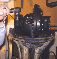
Put the pinion housing back in the vise. Place the bearing
cups over the bearings and set the ARB carrier back into the pinion housing,
meshing the crown ring with the pinion. |
 |
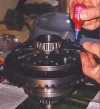
Lubricate the two rubber seals that came with the ARB (you
can use some of your 80W90 gear oil) and slide them onto the left side of
the carrier shaft. |
 |
The roll pins on the top of the carrier bearing cap should
be tapped up and out of the way. Set both carrier bearing adjusting nuts
onto the threaded portion of the pinion carrier and place the carrier bearing
caps on top of the adjusting nuts, ensuring that the bolt holes are lined
up. Tighten the adjusting nut to mesh the teeth of the crown and pinion.
Subsequent tightening of the opposite adjusting nut will push the crown
slightly away from the pinion, giving you some backlash (which you will
adjust later). Note that this second adjusting nut is replaced by the two-piece
ARB nut, which is drilled and tapped to secure the seal housing. (See step
34 for a photo of this nut.) |
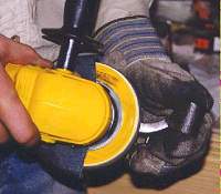 |
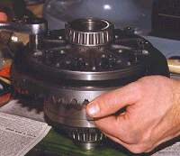
You may find that there is little or no clearance between
the carrier bearing caps and the carrier. If that's the case, you can grind
a little off of the inside of the carrier bearing caps. |
 |
Put in all four of the bearing cap bolts and tighten
a bit so proper alignment can be checked. Make sure the carrier still turns
freely. If it doesn't, it's probably binding on the bearing caps, which
will need to be ground off (See step 26 |
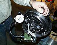 |
Mount a dial gauge on the side of the pinion housing to begin
checking the alignment of the differential. Rest the dial gauge stylus on
the back of the crown wheel to check the run out, which is the amount of
"wobble" the crown wheel has as it turns through a full rotation. The run
out should not exceed 0.004". If it does, you'll have to refit the crown
gear to the carrier, watching for dirt or burrs that may be throwing off
the alignment. Another possible cause can be crown ring bolts that are unevenly
torqued. |
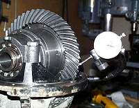 |
Next, position the dial gauge stylus on one of the teeth in
the crown ring. Hold the drive flange at the bottom of the pinion housing
and rock the crown ring back and forth to measure the backlash. Acceptable
backlash should be in the range of 0.004" to 0.007". If the backlash is
too much, loosen the cap bolts and adjust the nuts so that the crown ring
is pressed more firmly against the pinion. If too little, adjust the crown
away from the pinion. Note that you must tighten the bolts securing the
bearing caps each time before measuring backlash. |
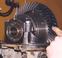 |
A final check of the correct gearing is made by spreading
Prussian blue over a section of the crown wheel gears. Make sure there is
a nice even coat over the gear teeth. You now have to rotate the gears keeping
some pressure on them. To do this, you can insert a flat tool between the
crown ring and the inside of the pinion housing to keep pressure on the
gears while turning the pinion from below. This will mark the section covered
with Prussian blue, showing the gear mesh. |
 |
Inspect the impressions made in the Prussian blue. If the
contact is too deep into the teeth, the crown gear is too far into the pinion
and should be moved farther away. If the contact is near the peak of the
teeth, the crown gear is to far away from the pinion and should be moved
closer. If the contact is on the outer edge of the teeth, there is too much
backlash. If the contact is on the inner edge of the teeth, there is not
enough backlash. If all is well, you should see a nice even contact pattern
in the center of the teeth. If you don't, you should loosen the bearing
caps, adjust the bearing adjusting nuts and retighten the caps. Then you
can repeat step 31 to check the alignment again. |
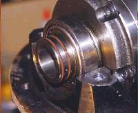
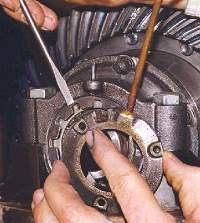 |
Install the seal housing (the piece with the copper tube coming
out of it) such that the notch is lined up with the roll-pin (straight up
as it sits in the vise) ensuring that the three holes for the hex-head screws
are lined up with the securing ring (what the screwdriver is pointing toward). |
 |
Secure the three hex-head bolts using Loctite, using the feeler
gauge to ensure a consistent gap between the seal housing and carrier shaft. |
 |
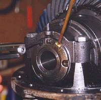
Lock the seal housing in place by tapping the roll-pins down. |
 |
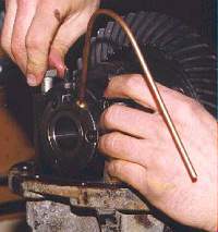
Run the copper tubing through the hole you have tapped in
the pinion housing, ensuring that it does not rub on the differential. |
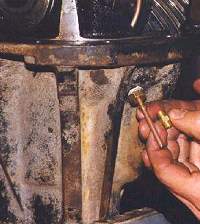 |
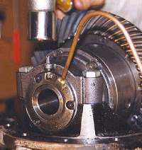
Assemble the 1/4" bulkhead body and the lower compression
nut as shown in the ARB instructions, and slide the assembled piece over
the copper tubing and thread it into the hole. Slide the proper brass ferrule
(yes there are two included and YES they are DIFFERENT) over the tube all
the way. Note, use Teflon tape on all threaded pieces. |
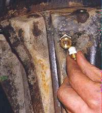 |
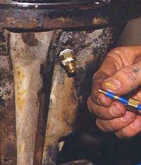
Cut the copper tubing flush with the 1/4" bulkhead body using
a Dremel tool or other method, being careful to deburr the edge once it
is cut. Place the central compression nut into the 1/4" fitting as shown,
noting that the shape of the inner surface of the ends are not the same.
The one with the deeper bevel faces the copper tubing. |
 |
Install the completed third member back into the axle casing
after using plenty of gasket sealer around the rim, and tighten the nuts
to the proper torque setting. |
 |
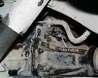
Assemble the blue plastic hose with its brass pieces as shown,
Pushing the small brass insert completely into the hose. Tighten the outer
compression nut over the ferrule to affix the hose to the differential. |
| |